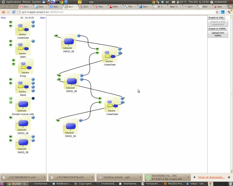
Figure 11.
The Lego-based approach made possible by MML and the MAD tool. Predefined software components (submodels, filters and mappers) visible on the left-hand side of the screen can be moved to the design window and connected through their input and output ports. These ports corresponds to the SEL operators and are represented with different symbols and colours. (Online version in colour.)

