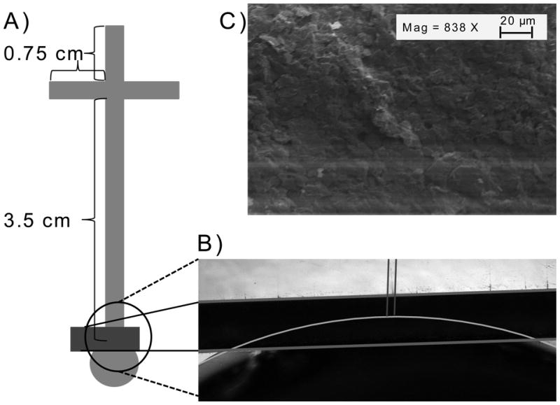
Figure 1.

A) A diagram of the PDMS microchip for ME-EC showing the dimemsions of the channels and the placment of the GPCE. B) A micrograph of the GPCE highlighting the electrode placement in the microchip. C) An SEM of the surface of the optimized GPCE.
