
Figure 1. Virtual grid to relocate the same region of interest.
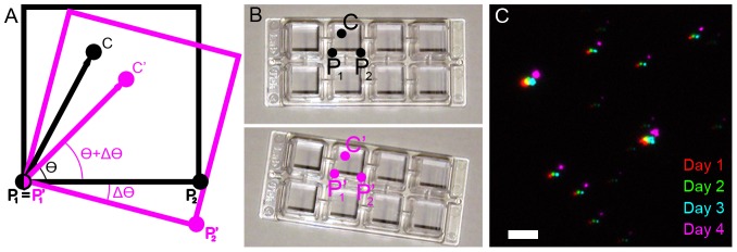
(A–B) During the first imaging session, the coordinates of two reference points are recorded (P1 and P2, typically the corner coordinates of the sample chamber as shown in B) as well as the coordinates of the region of interest, C. During the subsequent imaging sessions, the new coordinates of the reference points are recorded (P1' and P2') and these coordinates along with the previously recorded coordinates of the reference points and region of interest are used to calculate the new coordinates of the region of interest (C′). (C) Fiduciary markers (fluorescent beads) imaged on four subsequent days using the “virtual grid” approach to locate them. Scale bar 5 µm.