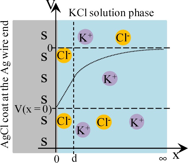
Figure 4.
The interface between AgCl coat at the Ag wire end and KCl solution. s represents the adsorption site on the AgCl surface. Some chloride ions are in the adsorbed state on the AgCl surface. Coordinate system is set as illustrated, where x = 0 represents the interface plane between the AgCl surface and KCl solution phase and x = d represents the plane of ion diffuse phase closest to the adsorption site of AgCl. V represents the potential, where V = 0 at x = ∞. Dotted line represents the potential behavior expected.

