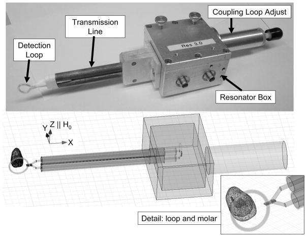
Fig. 1.
Top: A picture of an existing L-band resonator designed for tooth dosimetry (Walczak et al. 2005). The key components of the resonator are labeled. The detection loop is placed on the teeth and the transmission line connects the detection loop to inductively coupled loops in the resonator box. The coupling adjust knob is used to achieve the best coupling in the measurement environment. Bottom: A model used to simulate a resonator in HFSS. The direction of the static magnetic field, H0, is shown and is parallel to the Z-axis. The inset on the lower-right is a close-up of the loop and molar.

