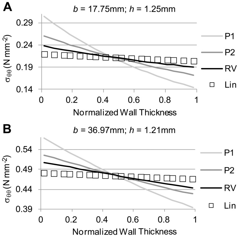
Figure 10. Comparison of circumferential stress distributions obtained using different tissue material properties in a tubular model.
Material properties employed were those listed in Table 1 (RV, P1, and P2), and results using the linear model (Lin) are also shown for comparison. For each panel shown, regardless of the material property employed in the model the deformed configuration (described by the outer radius b and wall thickness h) was the same, while the initial, unstressed configuration was adjusted. (A) Circumferential stress distributions obtained for the case of a small aneurysm. (B) Circumferential stress distributions for a larger aneurysm model.

