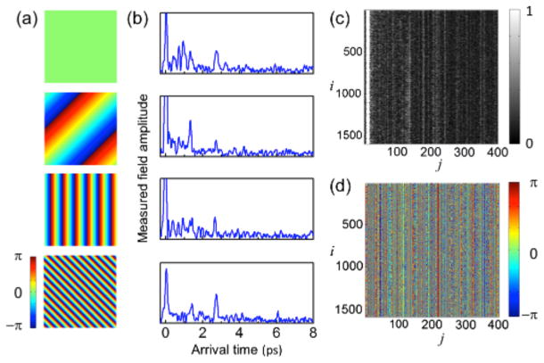
FIG. 2.
(color online). Measurement of TRRM. (a) Representative phase ramps written on the SLM. (b) Time-resolved reflection amplitude from a turbid medium for each incident channel shown in (a). The arrival time is a round-trip delay of light. Reflection from the first surface of a turbid sample is set as 0. (c) Amplitude part of the constructed TRRM. Indices i and j represent incident channel (phase ramp) and detection channel (time bin), respectively. Color bar: arbitrary units. (d) Phase portion of the TRRM. Color bars: phase in radians.

