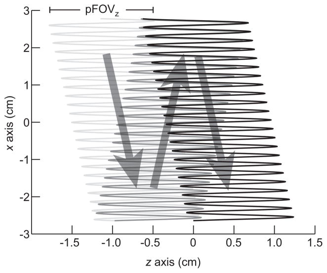
Figure 2. Imaging FFL trajectory for a single 2D projection scan.
Each projection image is produced through the application of slowly varying fields in x and z (in scanner coordinates), and a rapidly varying drive field in z. The signal is received only along the z-axis. 2D projection imaging does not require mechanical movement of the sample; however, the FOV can be optionally extended in the z-direction with a translation stage. Here, a sparse trajectory is shown for illustration purposes, while the actual scanning trajectory is considerably denser.

