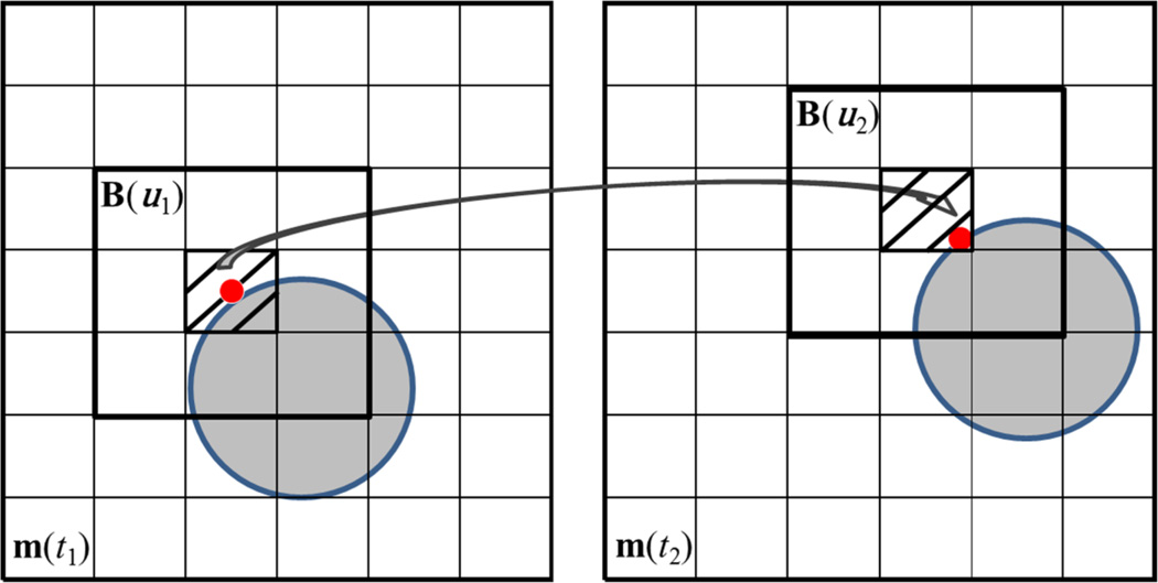
Figure 3.
Illustration of BLOSM block tracking. m(t1) and m(t2) are two consecutive images. An object (gray circle) is displayed on both images which underwent a translational shift (rightward and upward) from frame to frame. A red point is labeled on the circle to represent part of the object. A block B(u1) centered at the red point is initiated on m(t1). The red point is tracked from m(t1) to m(t2) using the ANTS toolbox, as shown by the arrow. Note that the tracked point on m(t2) is not at the center of the pixel. Instead of using spatial interpolation, the pixel containing the red dot (the shaded pixel) is selected as the new center pixel for the block. Then the neighboring pixels are included to form a tracked block on m(t2) as B(u2) where u2 = {u1 + Δu1}.

