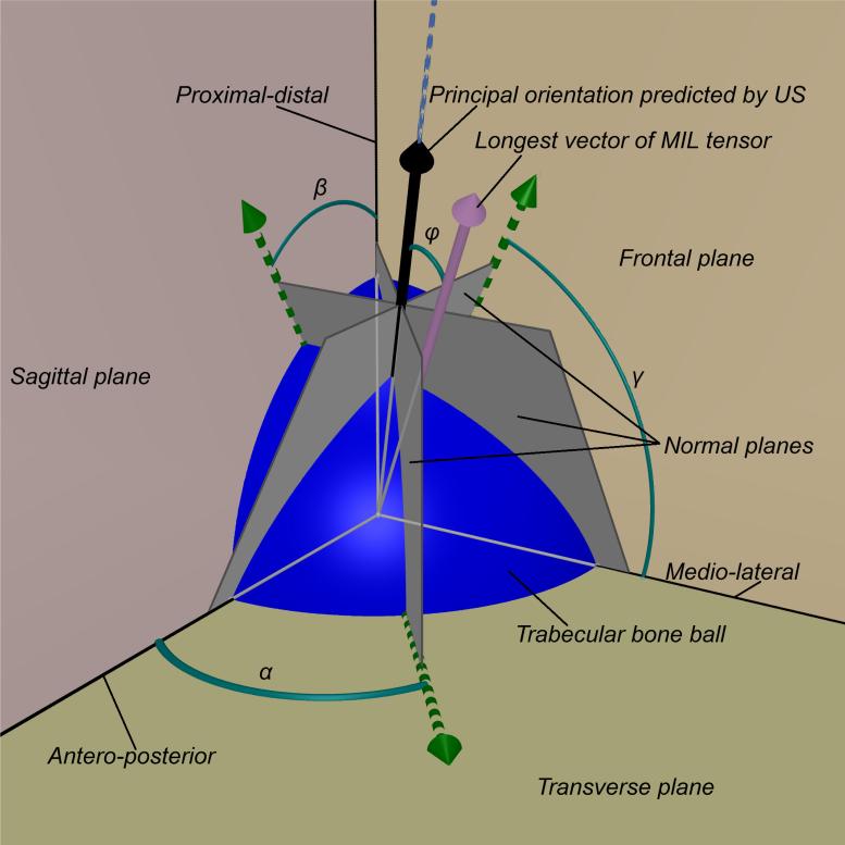
Figure 1.
The trabecular bone ball (blue sphere) was placed in a Cartesian coordinates system defined by the orthogonal anatomical planes (frontal, sagittal and transverse planes) with the center of the ball placed at the origin of the coordinates. Based on the rotational ultrasound measurement around 3 anatomical axes, the angles α, β and γ were determined. These are the angles in which the ultrasound measurements obtained peak values. According to these angles, three vectors (green arrows) on the corresponding orthogonal anatomical planes were determined, i.e., the vector on the transverse plane is determined by the ultrasound measurements around proximal-distal axis. Along the direction of each of these 3 vectors, a plane was defined normal to the corresponding anatomical plane. These normal planes (gray planes) intersect at one line (blue dash line). The normal vectors of these normal planes were used to define the intersection line using Equation 1 and Equation 2. A vector (black arrow) along the direction of that intersection line is defined as the principal orientation predicted by ultrasound, and the angle difference φ compared to the longest vector of MIL tensor (pink arrow) was calculated.

