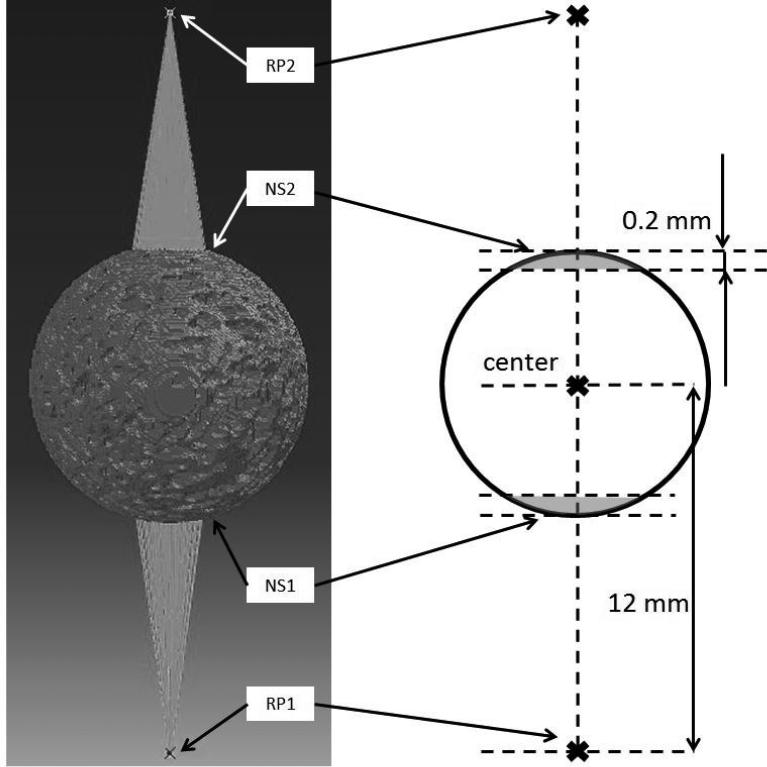
Figure 3.
For the boundary condition of the model, two sets of nodes (NS1, NS2) were defined to couple with two reference points (RP1, RP2). RP1 and RP2 were both 12 mm away from the center of the bone ball. The nodes in NS1 and NS2 (grey region in the schematic figure on the right) were respectively coupling constrained with RP1 and RP2 in all six degrees of freedom. During the loading, RP1 was encastred in all six degrees of freedom, and RP2 translated towards the center of the bone ball along the loading direction coupling with all the nodes in NS2 for 2,000 μstrain.

