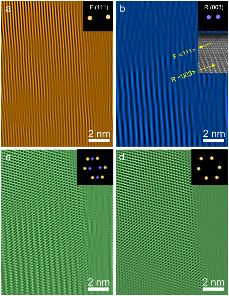
Figure 3. Inverse FFT images of an  /
/ composite particle obtained by placing masks on the FFT patterns.
(a) Inverse FFT image of  (111) planes before electron beam irradiation. (b) Inverse FFT image of
  (003) planes before electron beam damage, and the ADF-STEM image in the inset shows an example for the orientation relationship between the
  and
and  structures. (c) Inverse FFT image of the
  /
/ composite particle before electron beam damage. (d) Inverse FFT image of the
  /
/ composite particle after electron beam irradiation. The diffraction spots masked for inverse FFT imaging are shown in the insets, where the purple and yellow spots correspond to
  and
and  phases, respectively.

