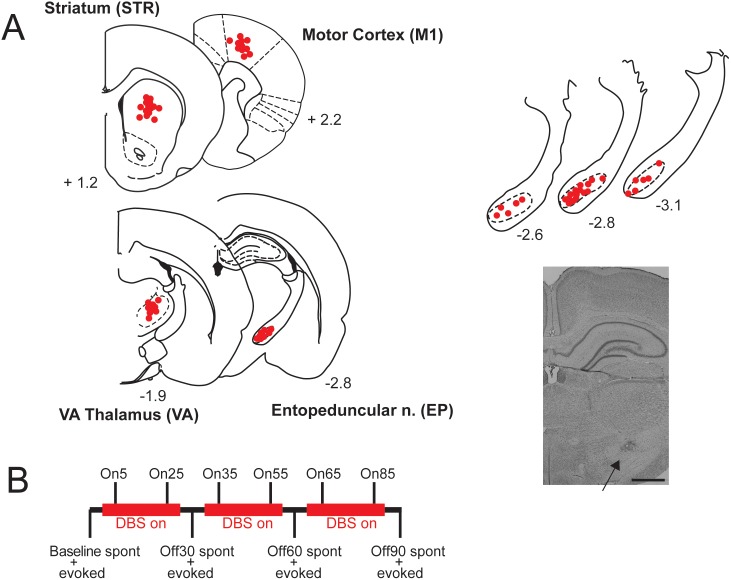
Figure 1. Electrode placements and experimental design.
A: Left: Dots show recording electrode placements in striatum (STR), primary motor cortex (M1), and ventroanterior thalamus (VA) and DBS electrode placements in entopeduncular nucleus (EP), and; numbers represent antero-posterior distance from bregma. Overlapping placements have been omitted for clarity, and placements have been collapsed into the same plane and may be slightly anterior or posterior (±∼200 µm) to the indicated distance from bregma. Right: Enlarged sections showing placements in EP and photomicrograph showing marked electrode location in EP. Scale bar = 1 mm. B: Outline of stimulation and recording protocol.

