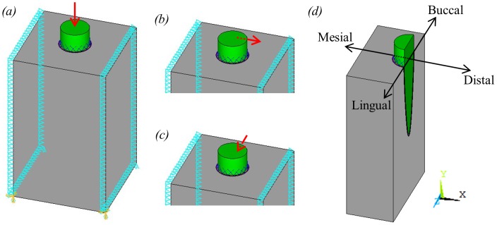
Figure 3. Tooth model showing loading and boundary conditions applied, where triangles represent constraints and red arrows represent applied forces.

(a) vertical occlusal load; (b) buccolingual orthodontic load; (c) mesiodistal orthodontic load; (d) section through centre of tooth model showing a typical plane from which strain results were taken.
