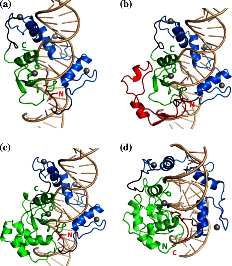
Fig. 4.
Designed ZFN structures, as starting points of MD simulations. The N-terminal part of NColE7 is shown in red, the C-terminal part in green, the ZF-s in blue, and the linkers are shown in black. The grey spheres indicate Zn2+-ions. a N4–ZF–C45 (reverse), b N46–ZF–C45 (reverse), c N4–ZF–C105 (reverse), d C123–ZF–N7 (straight). The C- and N-termini of the ZFNs are marked by “C” and “N”, respectively

