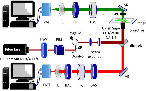
Figure 5.

Schematic diagram of the experiment set-up. For intensity measurement, both backward and forward channels are used to detect 2PF and SHG signals, respectively. For lifetime measurement, a photon-counting PMT is placed in the forward direction, and connected to a TCSPC system. HWP: half-wave plate, PBS: polarization beam splitter, L: lens, BA6: BA610IF, FG: FGS600, BA5: BA565IF, F: FF520, FBG: FBG39. M1, M2: mirrors.
