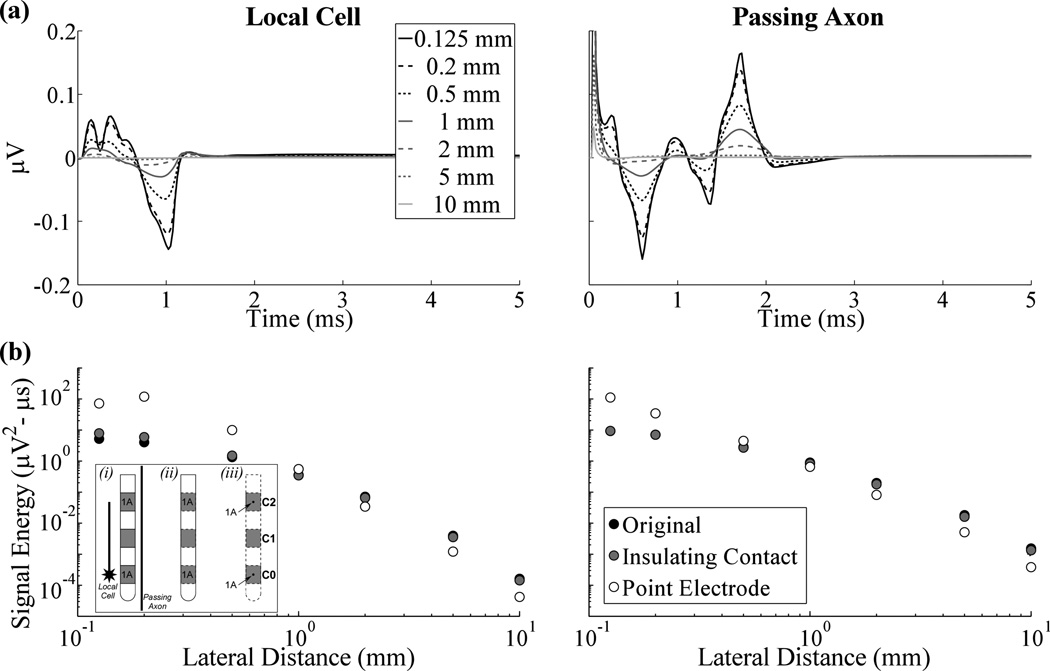
Figure 3.
Evoked responses measured from a single local cell or passing axon across electrode designs. (a) The evoked response at various lateral distances between the neural element and electrode using the dimensions of the Medtronic 3387 electrode with the original model. (b) Signal energy versus lateral distance for the original, insulating contact, and point electrode models, represented by black, gray, and white points, respectively. The lateral distance is measured to the location of the point electrodes for the latter model. The inset on the left is a cartoon describing the conditions used in the: (i) original model, with separate conductivities for the DBS electrode contacts and insulation, (ii) insulating contact model, in which the conductivity of contacts was set to that of insulation, and (iii) point electrode model, in which point sources were placed at the center of the contacts and the DBS electrode was no longer explicitly represented. Contacts 0 and 2 (C0 and C2) were recording contacts across the three conditions, and were set to 1 A in turn, with all other contacts set to a passive condition, to solve for the reciprocal FEM solutions and calculate the recorded neural signal. Separately, C1 was the stimulating contact and set to 1 V (with a distant ground) in the forward FEM model used to calculate potentials during DBS (not shown). The position of the single local cell or passing axon, relative to the DBS electrode, is shown in (i).

