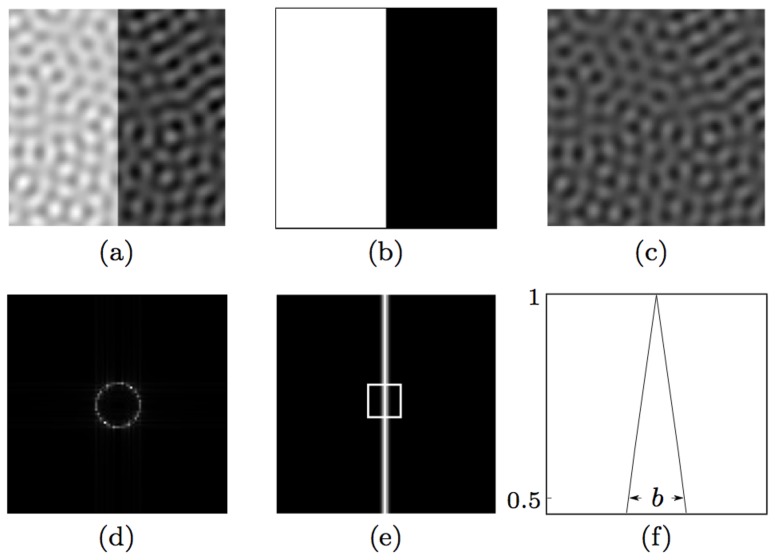
Figure 5. Construction of band-limited noisy images.
(a) A test image (of size 100×100 pixels) is the sum of a (b) noiseless edge image and (c) a noise image. The noise image is a superposition of a constant value N (here N = 8) and 100 sinusoidal gratings of randomly selected orientations for the same spatial wavelength w (here w = 9 pixels). (d) The 2D spectrum of the noise image in (c). (e) Response map that is obtained by CORF model cells (with or without inhibition) to the preferred stimulus in (b). (f) A horizontal profile within the enframed region in (e). The label b (here b = 3 pixels) indicates the number of CORF responses at half amplitude along the horizontal direction, which is the direction orthogonal to the edge orientation.

