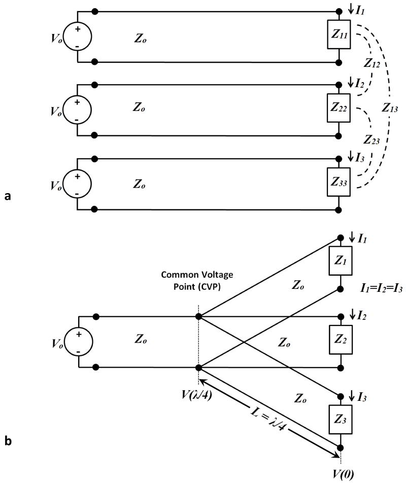
Figure 2.
Comparison of free excitation and forced current excitation (FCE). (a) Schematic illustration of three coils, identical or non-identical, excited by the same voltage. This configuration is termed “free excitation”. Asymmetries in positioning or environment, combined with the mutual impedances between coils generally leads to unequal load impedances presented to the sources, resulting in unequal currents despite identical excitation. (b) When connected to a common voltage point (CVP) by electrical quarter wave lines the feed currents are the same regardless of differences in the load impedances, effectively achieving “forced current excitation”.

