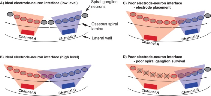
Figure 1.
Schematic of the electrode–neuron interface
Two cochlear implant channels are represented by gray rectangles, spiral ganglion neurons by gray ovals, and the edge of the osseous spiral lamina by a dashed line. The spatial extent of currents required to activate neurons for each channel are indicated by the gray shaded areas, respectively. (A) An ideal electrode–neuron interface is shown such that each channel activates nearby and nonoverlapping populations of neurons. (B) Higher stimulation levels produce broader spatial extents of currents and overlapping neural populations. (C and D) A poor electrode–neuron interface is shown as a result of placement of channel A near the lateral wall of the scala tympani (C) and as a result of spiral ganglion cell loss (D). Both scenarios require a higher stimulus current for Channel A to stimulate the closest viable neurons, resulting in broader excitation and greater overlap with the neurons activated by Channel B.

