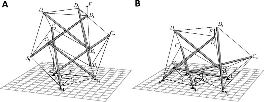
Fig. 5. Six-strut tensegrity model in the round (A) and spread (B) configurations.
The model is anchored to the substrate (gray grid) via nodes A1, A2 and A3 (round) and A1, A2, A3, B1, B2 and B3 (spread) indicated by black triangles. The black arrow at node D1 indicates the vector of applied force F. Increasing the number of anchored nodes results in a greater distension of the structure causing an increase in the structural stiffness, enhanced stiffening, and an increase in the average prestress in the cable elements. This behavior is consistent with the mechanical behavior observed in spread vs round cells (Ingber and Wang 1994). (Reprinted with permission from Coughlin and Stamenović 1998.).

