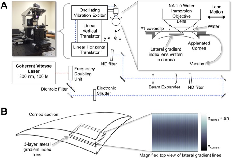
Figure 1.
Blue-IRIS experimental setup. (A) Pulses of 800 nm, 100 fs, from a Ti:Sapphire oscillator are frequency doubled to produce 400-nm, 100-fs pulses. These pulses are then attenuated and delivered through a 1.0-NA water immersion objective into the cornea of a live cat. The average power in the focal region of the objective is 60 mW. The cornea is applanated using a #1 microscope slide mounted on a custom-made suction ring. The focal region of the objective is scanned through the cornea using a three-axis delivery system to inscribe the Blue-IRIS pattern in the cornea. (B) A schematic of a corneal segment containing an inscribed, midstromal (280 to 300 μm below the epithelium), three-layer Blue-IRIS pattern. The inset shows a top-view representation of a single Blue-IRIS gradient index layer used to induce a negative change in cylinder with the largest positive refractive index changes at the top and the bottom (lightest shading), and the smallest RI changes in the middle of the structure (darkest shading). The resulting RI-change structure is intended to exert a phase-shifting effect on the incident light, with phase retardation increasing with increasing RI.

