
Figure 2.
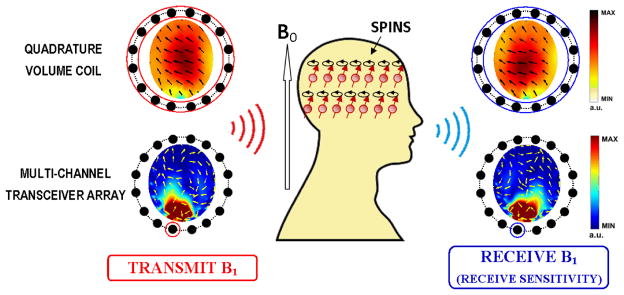
B1 field components on a transverse plane, when using a quadrature volume coil (3T; upper row) and a multi-channel transceiver array (7T; bottom row) for head imaging. In the transceiver array, a single coil element is used for RF power transmission and signal reception. Color maps indicate the magnitude of complex B1 fields, while arrows represent their phase variations in space (real part in horizontal direction vs. imaginary part in longitudinal direction).