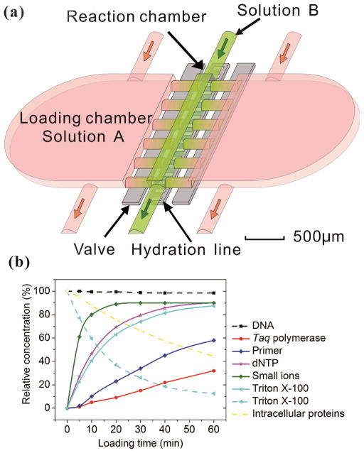
Figure 1.
Principle of solution replacement based on diffusion. (a) The design of the microfluidic device (with 24 nl reaction chamber). The device consists of two PDMS layers. Control and hydration are implemented in the same control layer by actuating the valves and supplying water under pressure (~25 Psi). The fluidic layer has a small reaction chamber connected with two large loading chambers. When the valves are open, molecules in the solution A may enter the reaction chamber by diffusion, effectively replacing solution B. (b) The entry (solid lines) and release (broken lines) of various molecules into/out of the reaction chamber, modeled by COMSOL Multiphysics. The initial concentration in the loading chamber (in the cases of entry into the reaction chamber) or that in the reaction chamber (in the case of release out of the reaction chamber) was used as the reference (i.e. having a value of 100%).

