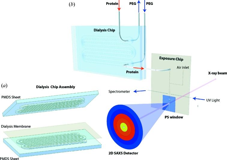
Figure 1.
Illustration of dialysis and exposure chip design. The setup consists of two microfluidic modules, the dialysis chip and the exposure chip. (a) The dialysis chip has two identical sides (albeit with varying channel depth) with channels for the polyethylene glycol and protein sample solution, respectively. The two sheets are clamped together with a dialysis membrane in between. (b) The outlet of the dialysis chip sample solution channel is connected to the sample inlet on the exposure chip. The exposure chip contains a UV cell and a SAXS exposure channel with a polystyrene (PS) window. An air inlet makes it possible to blow out old sample in the exposure channel and the UV cell.

