FIG. 4.

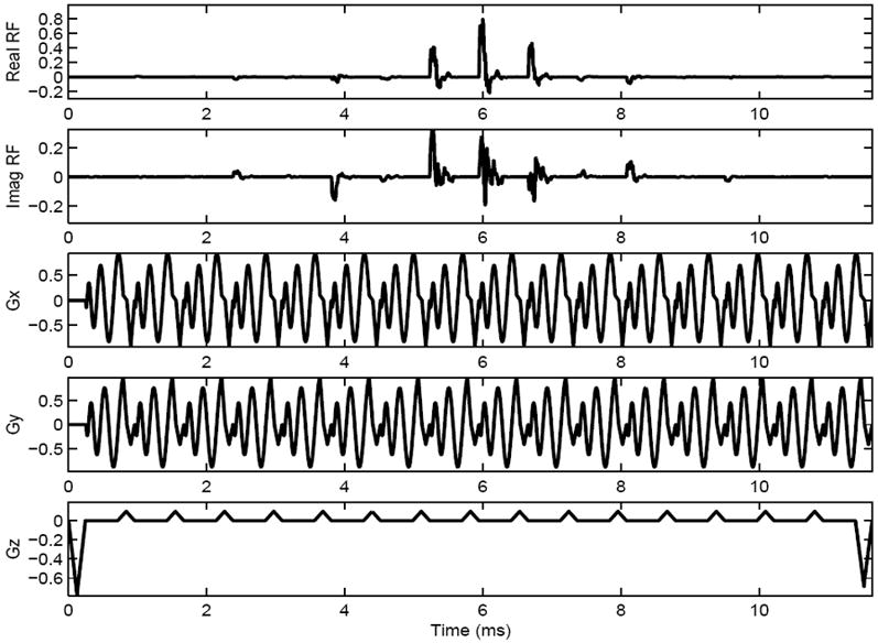
Diagram of one shot from a two-shot 3D TRF pulse with B1 inhomogeneity compensation tailored into the pulse. The rows from top to bottom are the real part of the RF, the imaginary part of the RF, the x-, y-, and z-gradients, respectively.

Diagram of one shot from a two-shot 3D TRF pulse with B1 inhomogeneity compensation tailored into the pulse. The rows from top to bottom are the real part of the RF, the imaginary part of the RF, the x-, y-, and z-gradients, respectively.