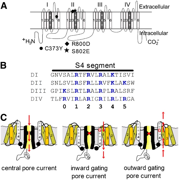
Fig. 1.
Diagrams of voltage-gated sodium channels. (A) Schematic diagram of sodium channel α-subunit Nav 1.5 (upper). The voltage-sensor (S4 segment) of each domain is shaded in gray and marked with “++”. The α-subunit contains three mutation sites: C373Y (filled circle), TTX-sensitive; R800D (filled diamond) and S802E (filled pentagon), HWTX-IV-sensitive. (B) Amino acid sequences of four S4 segments are aligned. The gating-charge residues (Lys/Arg) are highlighted in blue and the numbering scheme for these residues is shown below. (C) Schematic diagram depicting channel central-pore current (left panel), inward gating-pore current with central-pore current blocked (middle panel), and outward gating-pore current with central-pore current blocked (right panel).

