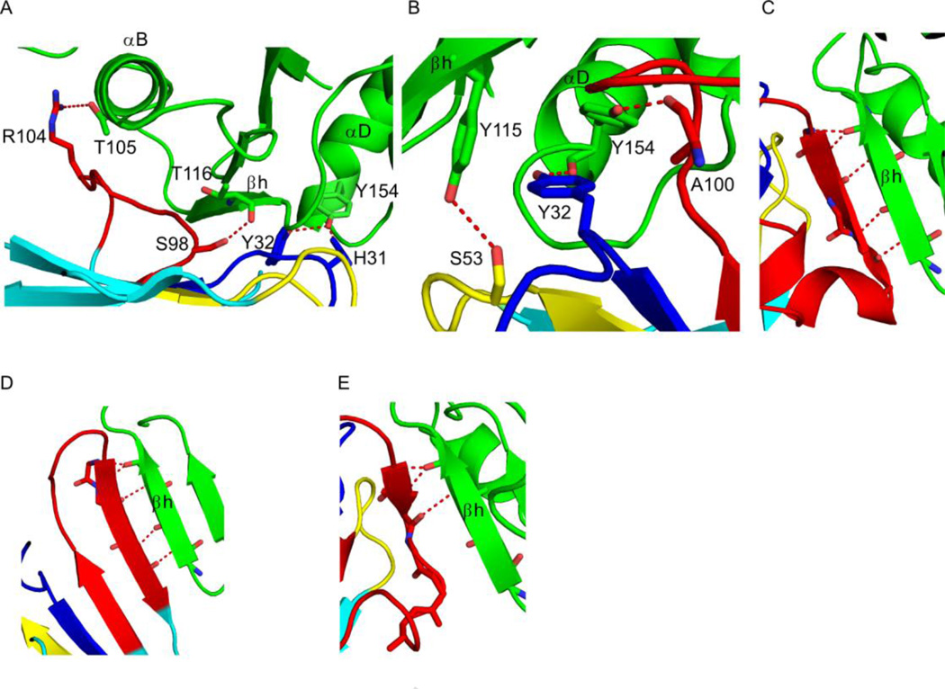
Figure 4. VHH interactions with key RTA secondary structural elements.
RTA (green) and VHHs (cyan) are drawn as ribbon diagrams. VHH CDRs 1, 2, and 3 are colored blue, yellow, and red, respectively. Side chains are drawn as sticks and color coordinated to the main chain color. Hydrogen bonds are represented as red dashes. (Panel A) Close-up of the interaction between VHH E5 and RTA’s secondary structural elements α-helix B (residues 97–107), β-strand h (residues 112–118), and α-helix D (residues 150–157). Only four (of a total of 16) of the hydrogen bonds in the interface are depicted for clarity. (Panel B) Zoom in of the interface between VHH D10 and RTA’s β-strand h (residues 112–118) and α-helix D (residues 150–157) portraying three (of a total of 13) of the hydrogen bonds in the interface. (Panels C–E) Main-chain hydrogen bond interactions between CDR3 from VHHs (C) G12, (D) G11, and (E) A7 with β-strand h (residues 112–118).

