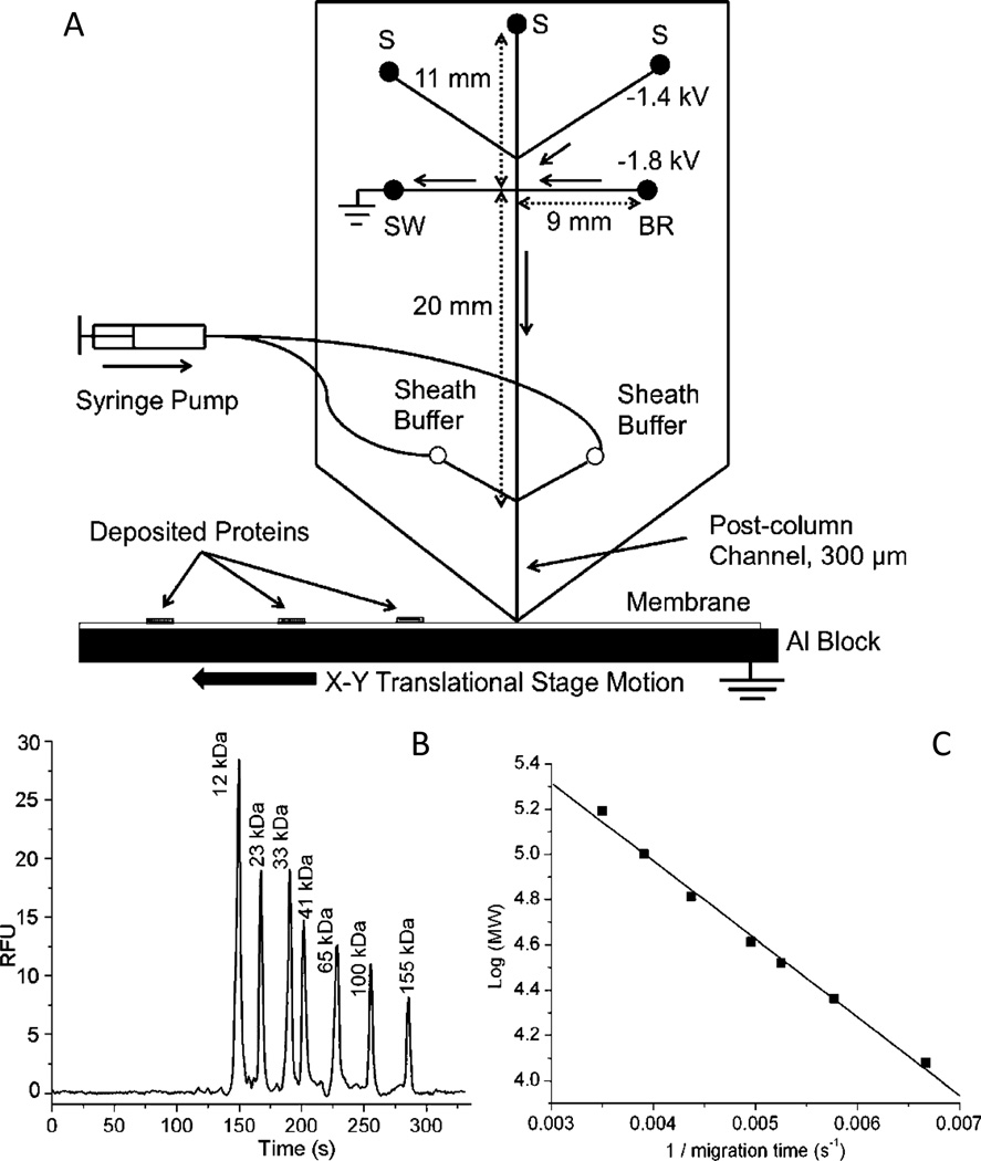
Fig. 8.
(A) Microchip overview. Samples are loaded in different sample reservoirs (S). Samples are injected by floating the buffer reservoir (BR) and sample waste (SW) with voltage applied between the desired sample reservoir and the Al block at the exit. During separation, flow from the sample reservoir is gated to the sample waste reservoir (SW) using the voltages as shown. During these operations, other sample reservoirs are floating. Sieving media is pumped through the sheath channels to give stable current. Channel lengths are indicated by double arrow lines and direction of flow during separation is indicated by solid, single arrows. B) Size-dependent separation of FITC-labeled protein ladder in microchips. Detection window was set at the end of separation channel, 300 µm away from the chip outlet. Electric field during separation was 240 V/cm. C) Relationship of MW to migration time. Reprinted with permission from ref. 140

