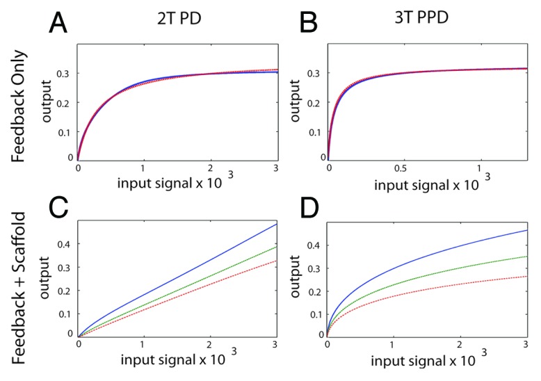
Figure 5. Generating an analog output from the MAPK module using feedback control and a scaffold protein. (A) The 2T P-D system (left panels) and the 3T P-P-D system (right panels) (B) in the presence of a negative feedback loop. The blue line shows the output generated in silico, the red dashed lines shows the output of an ideal Michaelis–Menten system, revealing that both the 2T P-D and 3T P-P-D system outputs closely approximate a Michaelis–Menten system in the presence of a negative feedback loop. (C) The signal output of the 2T processive-distributive module modified using a scaffold plus negative feedback loop (solid-blue-line; scaffold concentration = 1.0: dash-green-line; scaffold concentration = 1.2: dash-dot-red-line; scaffold concentration = 1.4). (D) The signal output of the 3T P-P-D module (solid-blue-line; scaffold concentration = 1.0: dash-green-line; scaffold concentration = 1.2: dash-dot-red-line; scaffold concentration = 1.4).
