
Figure 1.
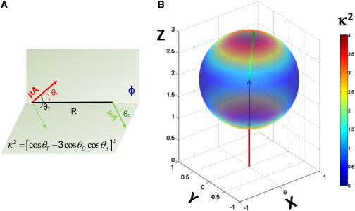
(A) Geometric definition of the dipole-orientation factor, κ2, as a function of the spatial relationship between donor and acceptor transition-dipole moments (green and red arrows, respectively). (B) Three-dimensional heatmap showing the dependence of κ2 on the polar angle between the donor transition moment and the vector between fluorophore centers of mass, . Here, the acceptor transition moment and are coaxial and oriented along the z axis. Under these conditions, κ2 can take on the full range of possible values from 0 to 4. Two extreme cases can clearly be identified in which the donor and acceptor transition moments are parallel (κ2 = 4) or perpendicular (κ2 = 0). (Two columns, 6.50″ W × 4.41″ H.) To see this figure in color, go online.