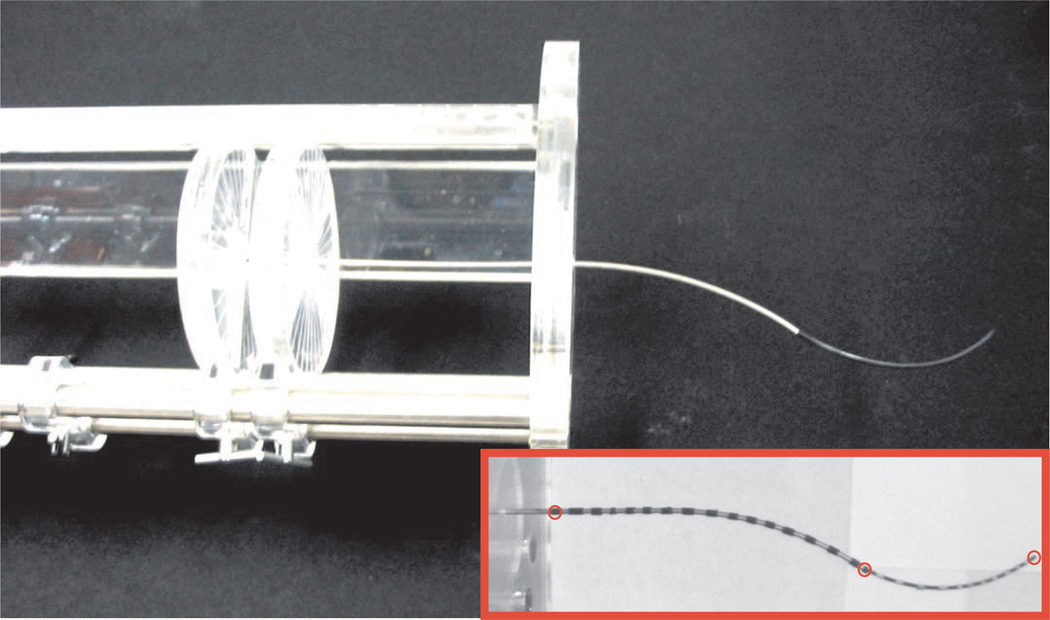
Fig. 8.
Manual actuation mechanism used in the experiments. In this apparatus, both tube and wire are affixed to circular acrylic input handles at their bases, which are etched to encode rotation. The support structure is etched with a linear ruler to encode translation. Spring pin locking mechanisms lock the input disks at desired linear and angular input positions. The inset image of a striped cannula on a white background is an example of an image captured using one of our calibrated stereo cameras. The black bands seen are electrical tape and allow for point correspondences to be identified for stereo triangulation. The red circles indicate the locations at which Euclidean errors were calculated. Calibration of model parameters was done to minimize the sum of these errors over all experiments.

