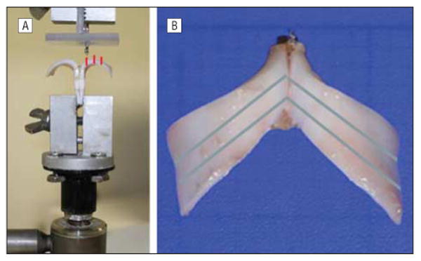
Figure 1.

Frontal (A) and axial (B) views of the mounted cartilage model. A, Frontal view of the cartilage model with a mechanical testing apparatus (ElectroForce Probe; Bose Corp) positioned 4 mm from the midline. The red lines indicate the 3 positions of the probe that were tested (4, 6, and 8 mm from the midline). B, Axial view of the cartilage model with the blue lines indicating incision lines for successive cephalic trims, with respective residual struts of approximately 6 mm after the first trim and 4 mm after the second trim.
