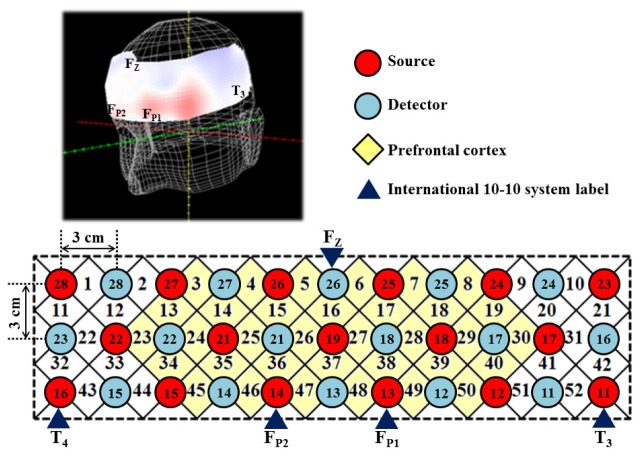
Fig. 1.
The fOT channels localization. (Top left) the 3-D image of the optode position; (Bottom) The localizations of all 52 channels were positioned according to the international 10-20 system. Red and blue circles indicate near-infrared light emitter and detector positions, respectively. By using the international 10-20 system the detector 26 was positioned at the FZ marker point while the bottom row of sources 11, 13, 14 and 16 were placed on the T3–FP1–FP2–T4 line. Yellow diamonds indicate the measuring region of PFC.

