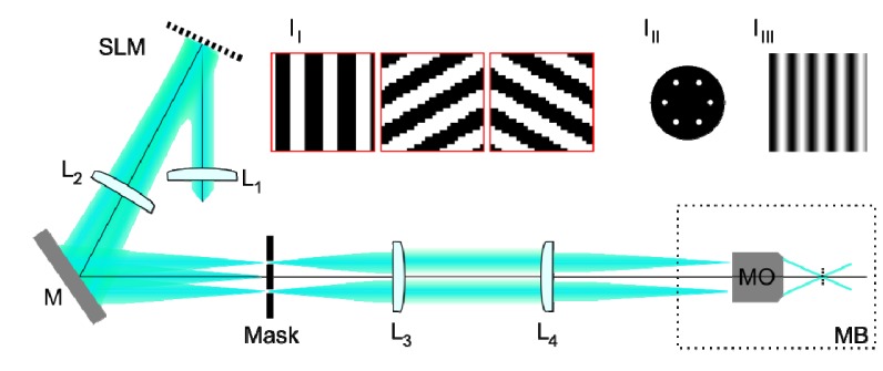
Fig. 2.

Schematic diagram of the SIM system used to acquire images for testing reconstruction algorithms. Lenses L1-L4 are achromatic doublets, SLM is a ferroelectric liquid crystal on silicon spatial light modulator, M is a plane mirror and MB is the microscope body. Inset I1 shows regions of the phase gratings displayed on SLM for 3 different excitation pattern orientations. Inset III shows the mask in the Fourier plane of the SLM used to select the positive and negative first diffracted orders. Inset IIII shows a sinusoidal intensity pattern at the focal plane of the microscope objective lens (MO).
