
Fig. 1.
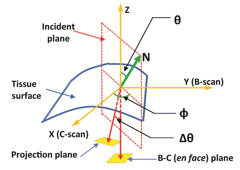
An illustration of image distortion induced by surface refraction. The incident light (A-scan) is aligned with the z-axis. (N) is the surface normal vector at the light incidence point. The en face x-y plane formed by the B- and C-scan are equivalent to the histology sectioning plane. The incident light is deviated by Δθ within the incident plane (formed by the incident light and the surface normal vector) due to optical refraction at the sample surface.