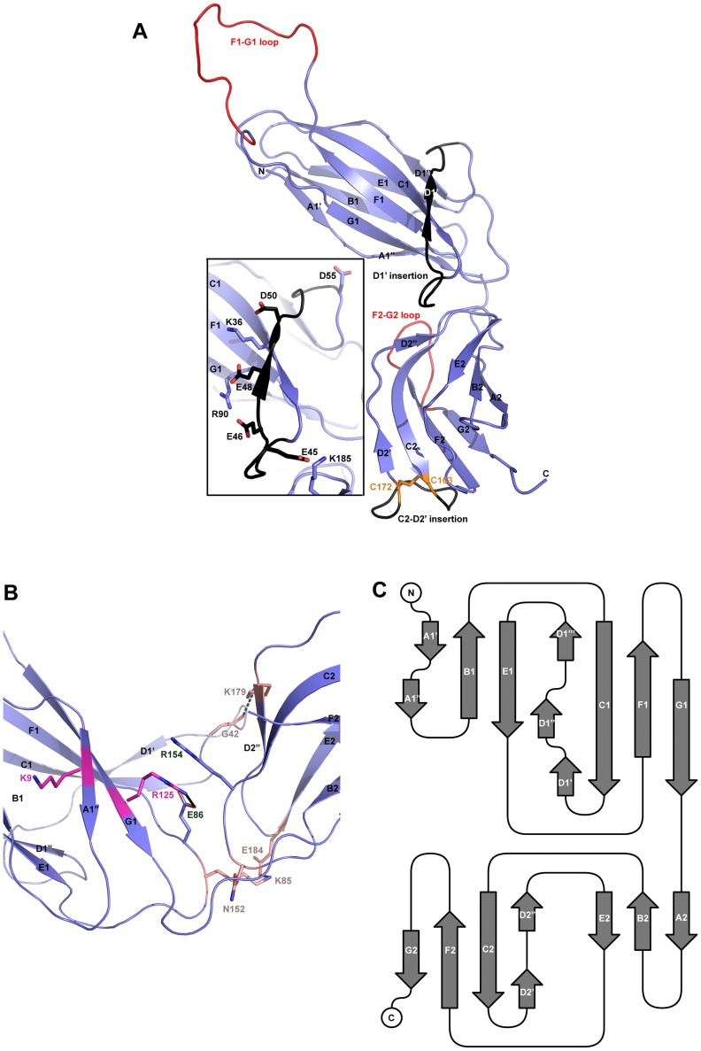
Figure 1. Structure of CfaA chaperone of Class 5 fimbriae.
(A) Ribbon representation of the structure of monomeric CfaA. The seven strands in the N-terminal domain are labeled sequentially from A1–G1, and similarly in the C-terminal domain as A2–G2. Those segments in the G1–F1 and G2–F2 loops, which are crystallographically disordered, are shown in red. Insertions such as the D1′ and C2–D2′ insertions that are unique to Class 5 family chaperones are colored black and labeled. The disulfide bridge stabilizing the C2–D2′ insertion is shown as stick model in orange and labeled. Inset: detailed charge interactions in the acidic D1′ insertion is displayed. Five acidic residues in the insertion are shown as stick model (carbon atoms in black and oxygen in red), as are the interacting basic residues (with carbon in light blue and nitrogen in dark blue). (B) Interaction in the cleft formed at the interface between the N- and C-terminal domains of CfaA, showing interactions by charged residues in stick models with nitrogen in blue and oxygen in red. Residues K9 and R125 are shown with carbon in light magenta. Residues E86 and R154 are shown with carbon in light blue. Other interacting residues are shown with carbon in orange. (C) Schematic diagram depicting the topological arrangement of β-strands in CfaA structure.

