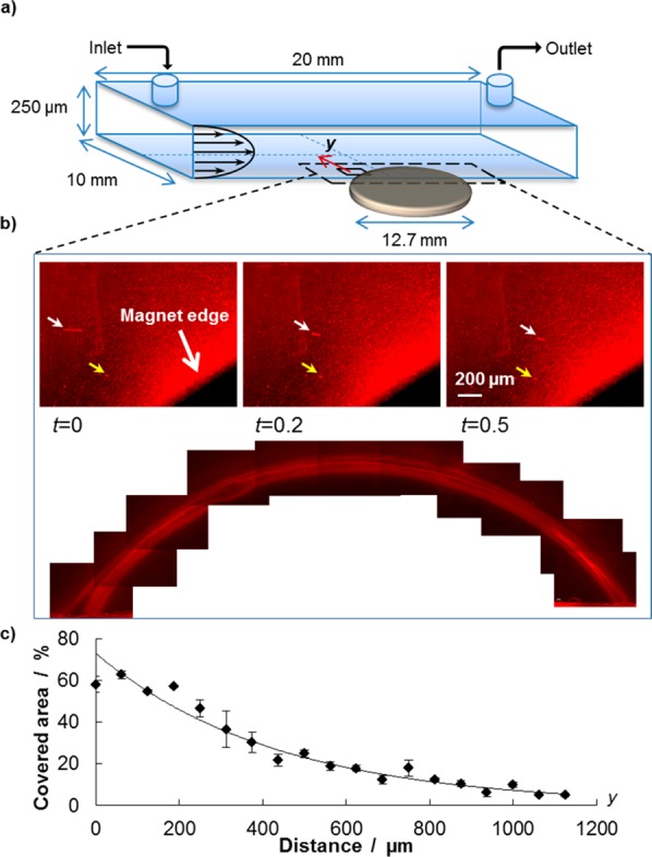
Figure 3.

Remote guidance of the Magnetic NanoFlakes (MNFs): (a) Schematic representation of the parallel plate flow chamber used for the experiments. A static magnet is placed underneath the chamber for the dragging experiments under flow. (b) Three individual images show the path of two individual MNFs under flow (yellow and white arrow) at three consecutive time points; also, a fluorescent corona is formed around the magnet by the MNFs continuously depositing. The image is obtained by stitching together multiple pics taken from the unmounted coverslip after the experiment. (c) Percentage of area covered by the deposited nanoparticles is plotted as a function of the separation distance y from the magnet edge. Up to 5% of the area is covered by MNFs at ∼1 mm away from the magnet.
