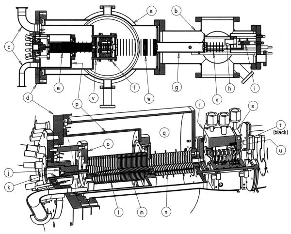
Fig. 13.
(Top) Cross-sectional view of entire electrospray ion mobility mass spectrometer as viewed from the top. (Bottom) Perspective cross-sectional view of source, funnel, and cell. (a) and (b) vacuum chambers, (c) pump ports, (d) source flange, (e) ion funnel, (f) drift cell, (g) quadrupole mass analyzer, (h) conversion dynode, (i) detector, (j) capillary heating block, (k) insulator, (l) funnel first section, (m) funnel second section, (n) funnel third section, (o) funnel flange, (p) hat flange, (q) second pump stage, (r) cell body, (s) cell end cap, (t) ceramic ring, (u) guard rings, and (v), (w), (x) ion optics. Figure reproduced from ref. [93].

