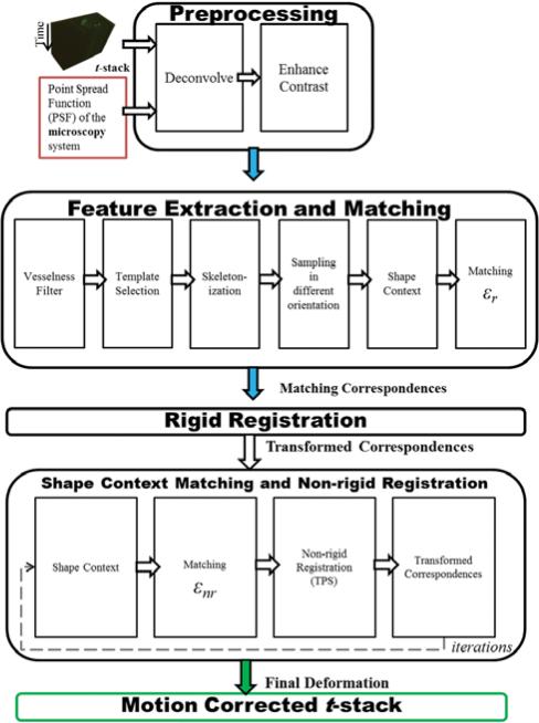
Figure 1.
Flowchart showing the major blocks of the algorithmic framework. The primary input into this framework is the t-stack or time-series image stack acquired from a Zeiss LSM 5 LIVE microscope. The top section of the block diagram describes the involved preprocessing steps for the t-stack before the feature extraction and registration steps can occur. The middle section of the block diagram details the elements of developing a robust feature descriptor before matching correspondence pairs can be formed. These matching correspondence pairs are used in a rigid registration step to yield a transformed set of correspondence pairs, which account for large movements in t-stacks. The bottom section of the block diagram specifies the connections and the iterative flow between the nonrigid registration segment and SC matching step. The final output is the motion corrected t-stack.

