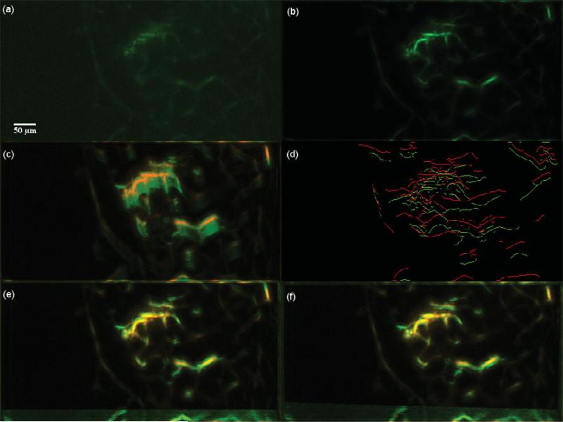
Figure 14.
Suboptimal case. Dataset 4, 450 frames, “most” movement at depth z0 = 40.400 μm. (a) A frame of the original t-stack. (b) The template used for performing motion correction. (c) The template (red channel) superimposed on the MIP (green channel) of the uncorrected t-stack. (d) Hysteresis results of the template superimposed with a frame of the uncorrected t-stack. (e) The template (red channel) superimposed on the MIP of the motion corrected t-stack (green channel) using the baseline algorithm. (f) The template (red channel) superimposed on the MIP of the motion corrected t-stack (green channel) using the presented algorithm. From panel d, the sampling process is compromised by the poor hysteresis response leading to a not so sharp overlap of the MIPs of template and the motion corrected t-stack.

