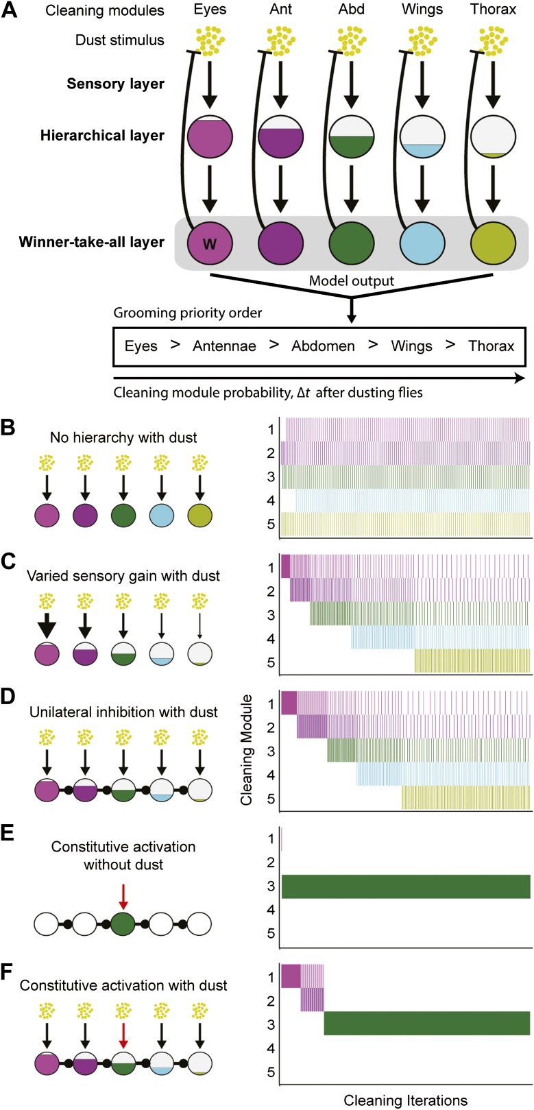
Figure 4. Model of hierarchical suppression results in the sequential progression of grooming.
(A) The dust induced grooming sequence requires three layers: (1) the sensory layer detects dust and independently activates each cleaning module. This is shown as parallel excitatory arrows from each yellow dust cartoon to activate specific cleaning modules. (2) The hierarchical layer determines each module's level of activation when its respective body part is coated in dust. Circle fill levels show theoretical differences in the relative activation levels of the modules. (3) The winner-take-all layer selects the cleaning module that is most active and suppresses all competing responses (‘W’ in this layer shows that the eye cleaning module is selected first). Theoretical all-to-all inhibitory connections in this layer are depicted as a gray box for simplicity. Blunt arrows from the winner-take-all layer to the yellow dust depict that the winning module reduces its own sensory input by cleaning off the dust and consequently becoming less active. The cleaning continues until the activation level of the module is no longer maximal, at which point the transition of cleaning to the new maximally active module occurs. Multiple iterations of this process result in a sequential progression. (B–D) Computational model simulates possible implementations of the hierarchical layer in establishing the most active modules. Modifications to the hierarchical layer and sensory inputs are depicted in each diagram. In this simulation, the competition is between five different cleaning modules. The ethograms show typical results of the simulation, where each row corresponds to the output of a module. (B) Equal sensitivities to dust and no inhibitory connections. (C) Modules with varying sensory gain in response to dust: modules with higher sensory gain (depicted with thicker arrows) have higher activation levels in response to the same dust amount. Fill levels represent the relative activity levels of the modules at the first iteration of the simulation. (D) Unidirectional lateral inhibitory connections between the modules. For simplicity of illustration, only the nearest-neighbor inhibitory connections are shown; in the computational implementation, each module inhibits all the subordinate modules in the hierarchy (e.g., 2 inhibits 3, 4, and 5). (E) Constitutive activation of a single cleaning module. Simulated by setting the amount of dust on a particular body part to completely dirty after each round of cleaning (depicted with the red arrow). (F) Constitutive activation of a single cleaning module in the presence of dust on all body parts.

