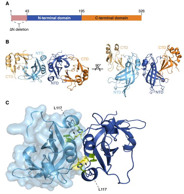
Figure 1. The dimeric structure of VP40.
(A) A schematic of VP40 showing the location of the N-terminal 43 residue deletion in VP40SΔN and VP40EΔN and the NTD (blue) and CTD (orange). (B) The VP40EΔN dimeric crystal structure is displayed with the NTDs from each protomer colored light or dark blue and CTDs light or dark orange. (C) The VP40EΔN dimeric interface displaying residues A55, H61, F108, A113 and M116 (green) and L117 (yellow). The surface representation on the light blue protomer illustrates how L117 reaches into the opposing protomer. See also Figure S1 and S2.

