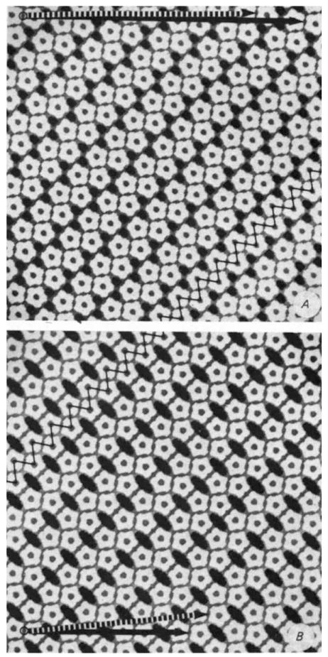
Fig.3.
Comparison of the pentamer packing in hexamer (A) and pentamer (B) tube surface lattices illustrates correspondences in bonding contacts. The ‘zig’ and ‘zag’ lines (oriented respectively nearly vertically and horizontally along the diagonally directed ribbon) indicate the two classes of dimer ‘bonds’ between pentamers that are conserved in the hexamer and pentamer tube lattices. These planar models were constructed with equivalent connections for the differently oriented edge-to-edge bonds between the pentagonal units, and the packing width of the zigzag ribbon in A was made the same as in B. In the cylindrically curved tube surface, the differently oriented edge-to-edge contacts are non-equivalently bent. Furthermore, the relative separations of capsomeres in the different bonding directions measured from electron micrographs are slightly distorted compared to these idealized models. Circumferential vectors corresponding to different tube structures are marked by arrows between equivalent lattice points. Models of the tubes can be constructed from these plane lattices by cutting out rectangles based on the circumferential vectors and connecting the vertical edges to form cylinders. Two of the frequently observed size of hexamer tubes are indicated by the arrows at the top of A. the dashed one representing the circumference of the tube in Fig. 1A. Hexamer tubes of larger and smaller diameter have circumferential vectors in approximately the same direction as the marked arrows. The circumferential vectors of the zero- and one-start pentamer tubes4 (which are the only identified narrow tubes of this type) are marked by the solid and dashed arrows, respectively, at the bottom of B.

