
Fig. 5.
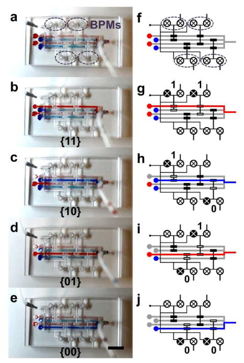
(a) A 4-to-1 microfluidic multiplexor chip with 4 BPM devices. (b-e) Flow source is switched from different reservoirs. (f-j) Illustrations depicting the BPMs involved in the flow switching and the corresponding address codes. (scale bar: 5 mm)