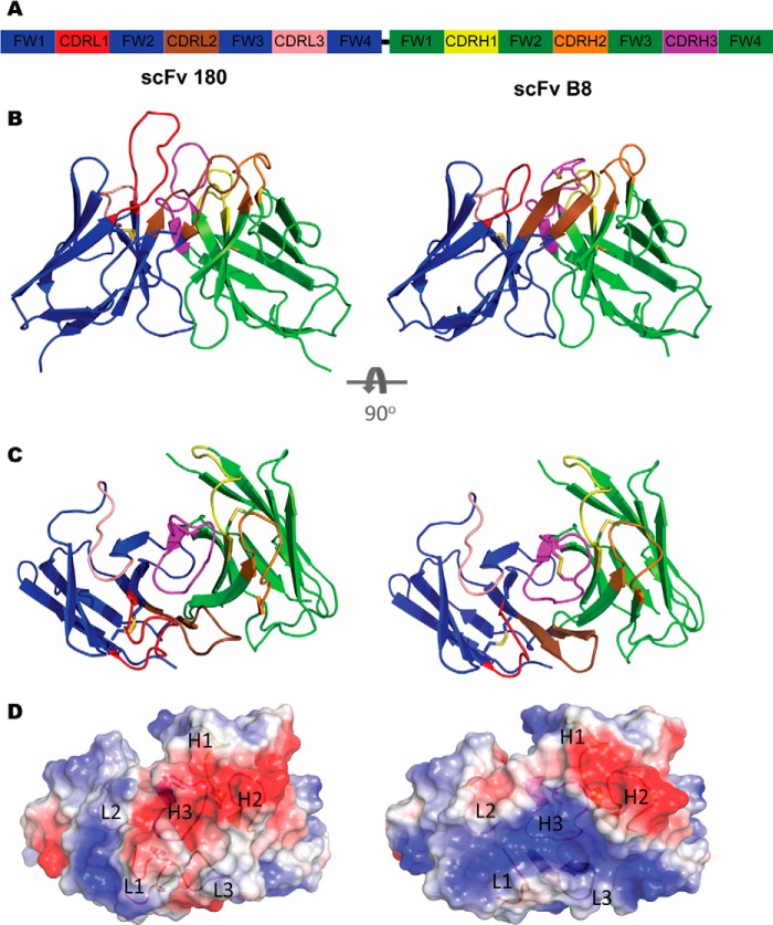
FIGURE 4.
Structures of scFv 180 and B8. A, diagrammatic representation of the scFv format colored by chain (VL, blue; VH, green) with the CDR L1 (red), L2 (salmon), L3 (brown), H1 (yellow), H2 (orange), and H3 (magenta) shown. The flexible linker (black) connects the C terminus of the VL to the N terminus of the VH but was not modeled in the solved structure. B, ScFv 180 is dominated by the CDRL1 and H3, which protrudes into the solvent, creating a grooved binding site that is typical of an anti-peptide antibody. The CDR arrangement of scFv B8 is more compact creating a “shelf-like” arrangement for antigen binding. C, the antibody binding sites as viewed from the antigen perspective. D, the transparent electrostatic surface view of the scFvs, from the antigen perspective, with the CDR loops visible. The positively and negatively charged areas are indicated in blue and red, respectively. ScFv 180 has a predominantly negatively charged pocket that is largely attributed to CDRs L1 and H3. In contrast, scFv B8 has a predominantly positively charged surface.

