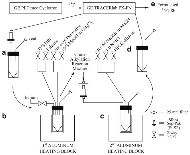
Scheme 1.
Diagram shows connection between the cyclotron, primary and secondary synthesis modules. a 5-mL collection vial receives [18F]-3b after solid phase extraction with Si-SP. b The vial with [18F]-3b is placed into aluminum heating block for the subsequent bromination and alkylation reactions. c [18F]-7a and [18F]-7b are eluted through a Si-SP to a second 5-mL vial for the remaining deprotection step in another heating block. d The vial containing the crude deprotected product is reattached to the 1° module for HPLC purification and product formulation. e Formulated [18F]-8b is sterile filtered into a sterile multidose vial.

