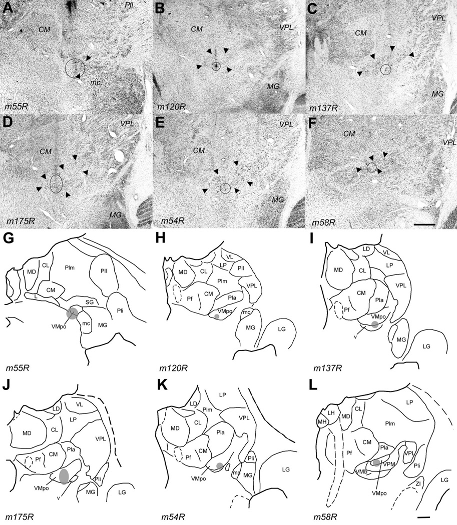
Figure 7.
The injection sites in the six cases that demonstrate the topographic organization of the VMpo projection to dorsal posterior insular cortex. The top panel (A – F) shows for each case a photomicrograph of the coronal thionin-stained section in which the histological trace of the micro-pipette and the micro-injection placement are best seen. A solid circle or oval indicates the outline of the micro-injection , as seen in that or an adjacent (fluorescent) section; the large arrowheads indicate the cytoarchitectonic boundaries of VMpo. The lower panel (G – L) shows for each case a line drawing of the section shown above; together, these demonstrate the placement of each micro-injection at a different antero-posterior level of VMpo, progressing from a very posterior level (upper left, A and G, case m55R) to a very anterior level (lower right, F and L, case m58R). Bar = 1 mm for both. Abbreviations: CL, central lateral nucleus; CM, centre median; L, nucleus limitans; LD, lateral dorsal nucleus; LG, lateral geniculate; LH, lateral habenula; LP, lateral posterior nucleus; mc, magnocellular part of the medial geniculate; MD, medial dorsal nucleus; MG, medial geniculate; MH, medial habenula; Pf, parafascicular nucleus; Pla, anterior pulvinar; Pli, inferior pulvinar; Plm, medial pulvinar; R, reticular nucleus; SG, suprageniculate nucleus; VL, ventral lateral nucleus; VMpo, posterior part of the ventral medial nucleus; VPL, ventral posterior lateral nucleus; VPM, ventral posterior medial nucleus.

