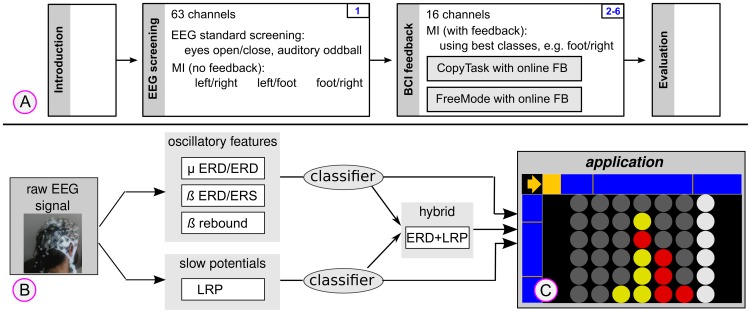
Figure 1. The experimental design is shown in plot (A).
Plot (B) depicts the architecture of the flexible BCI system which simultaneously considers oscillatory features and slow potentials. Two classifiers are applied and the feedback application is receiving simultaneous output of both classifiers and their weighted combination. A screen shot of the “Connect-4” application in mode FR (foot vs. right hand) is plotted in (C). In the top-left corner, the cue is presented (an arrow pointing to the right) and based on the BCI output, the yellow bar is either extending rightwards or downwards. The rightmost column is currently selected and visually highlighted.

