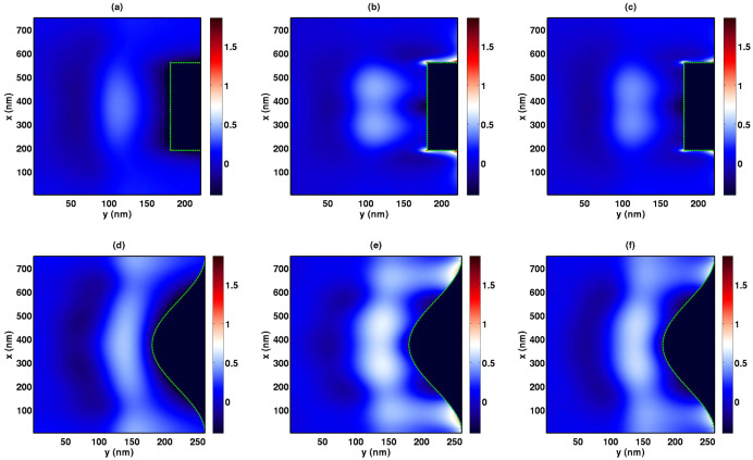
Figure 4. Abnormal exciton generation obtained from the theoretical model.
The graphs present the exciton generation of the Ag-grating-inverted devices over that of the Ag-planar-inverted ones, which is defined as log10(Gg(r)/Gp(r)). The active layer thickness for both types of devices is set to be the same. The exciton generation of the Ag-planar device is nonzero at the region corresponding to the nanopatterned anode of the Ag-grating device where zero exciton generation is achieved. (a) s polarization for the square grating; (b) p polarization for the square grating; (c) unpolarization for the square grating; (d) s polarization for the sinusoidal grating; (e) p polarization for the sinusoidal grating; (f) unpolarization for the sinusoidal grating.

